Adding an RGB switch to my TV
I have a flat screen TV I bought in 2009. I use it for various retro computer things, mainly when I'm travelling and don't want to carry a CRT around. It is also useful because the VGA port will accept any timing, down to the 18KHz refresh rate of MDA/Hercules at least. It also has a few other cool things my CRTs will not do, like Teletext support.
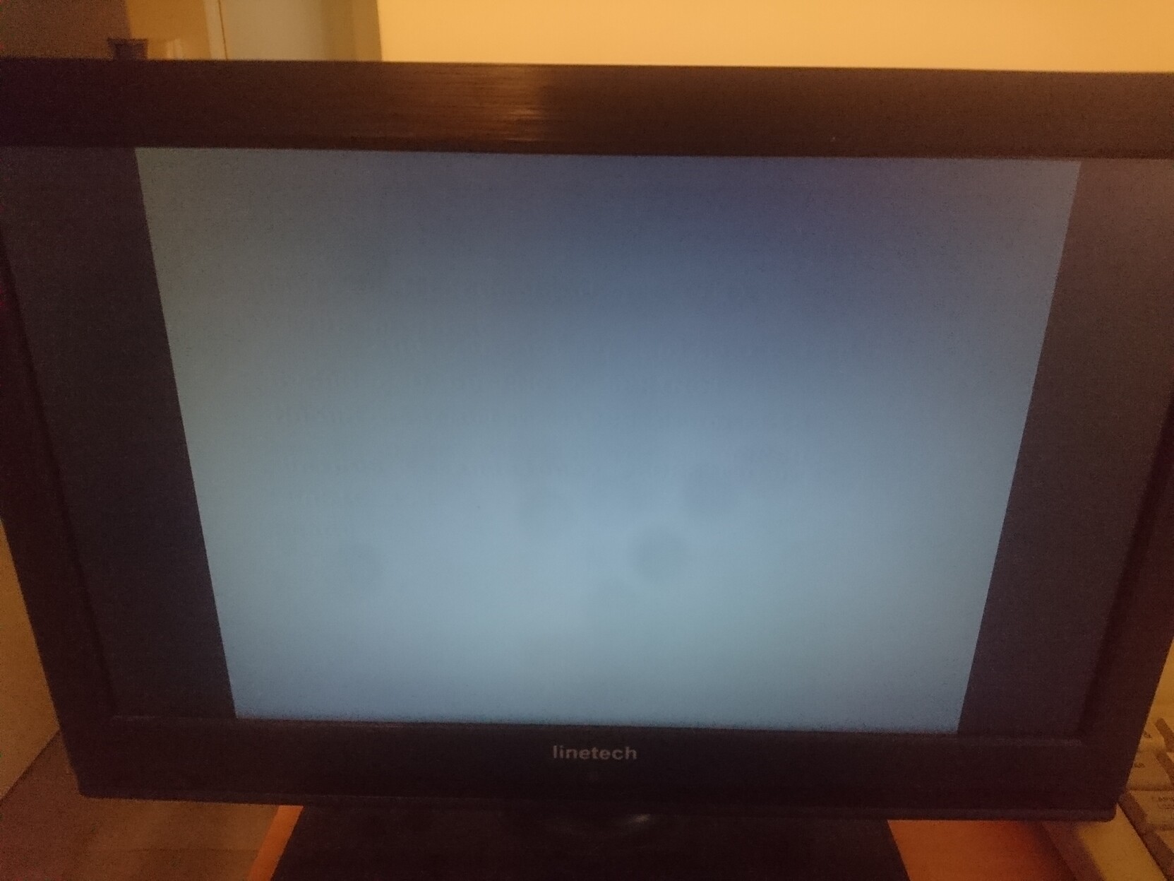
There is just one problem with it, however: there is no way in the menus to force the SCART connector into RGB mode. This can be done only by sending the proper voltage (1 to 3 volts) to the SCART connector itself. Normally this isn't a problem: proper RGB SCART things will send that voltage, and everything will be fine. But I also want to use this port for other stuff, where I make an adapter myself for some other type of RGB output. Often there isn't a voltage source available on the power connector then. As a result, the TV switches to composite mode and shows a grey screen (since it uses the sync signal as a video signal, and so there is nothing to show).
Previously I did this as an external mod: getting 5V from the USB port of the TV, and feeding back into the SCART. But this requires making SCART connectors with a 5V input, the cable can break when transporting the TV... well, it's annoying. So I decided to make it internally instead.
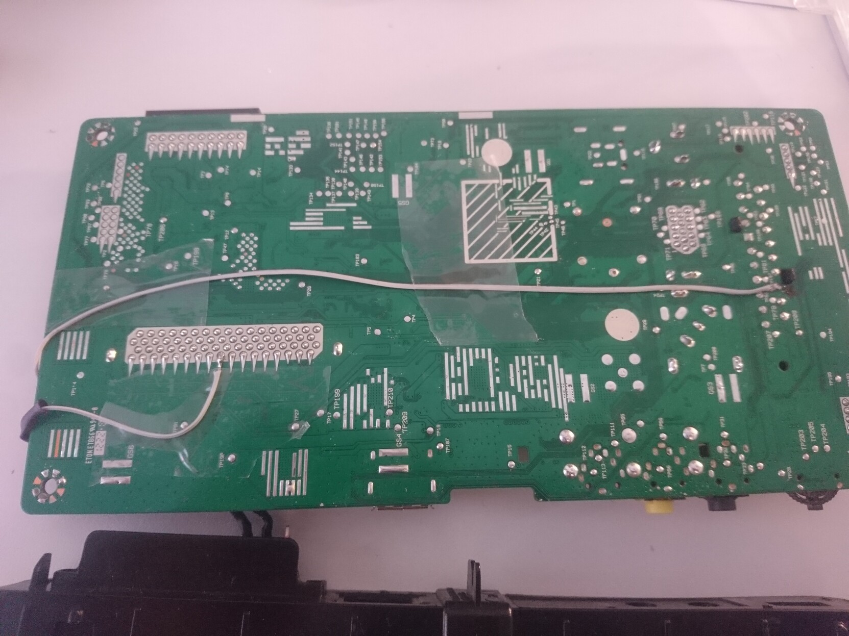
I get the 5V from the Common Interface slot, this is a PCMCIA slot where you could plug a satellite TV receiver or crypted TV decoder or the like. Since this has a standard pinout, the 5V was easy to locate, and also they made it with very large soldering pads so adding a wire there was very easy.
Since the TV expects 1 to 3V on the RGB switching line, I use a 220 ohm resistor. The TV has a 75 ohm impedance, so this creates a voltage divider in the right range. Any resistor from 50 to 300 ohms would do.
Finally, I mounted the switch by screwing it into the Common Interface slot. The slot is just wide enough to put the switch through, and will provide enough mechanical support once the switch is secured there.
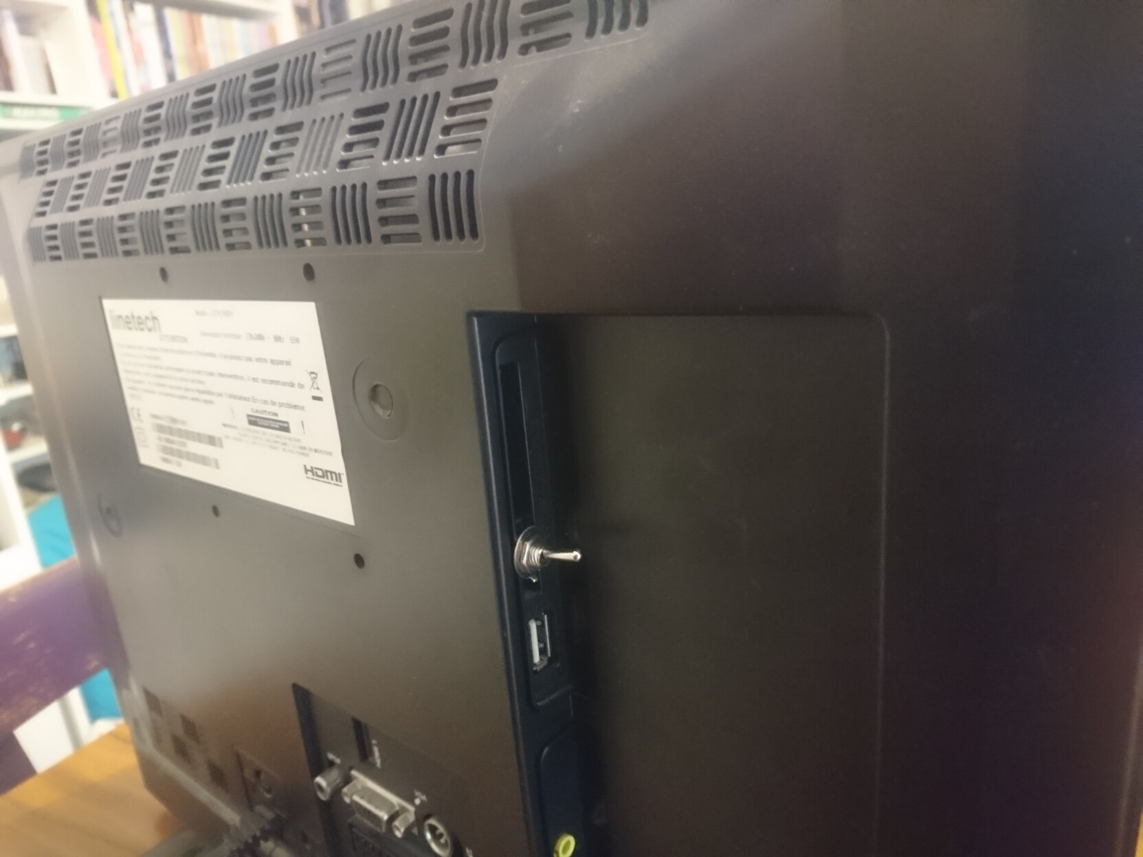
When the switch is ON, this will force the TV to use RGB input on the SCART port. When it's off, the TV will work as normal since the mod is disconnected. A quite simple change in the end, but very useful for me.
